Hardware configurations
Introduction
This document describes the typical hardware configurations of Focus Virtual Studios and the main features of their work and adjustment.
Focus Studio formed from the basic systems on the platform of Microsoft Windows © with a special expansion cards - graphics accelerators and Input-Output boards. System components are specially selected and tested to ensure adequate application performance, reliability and cost. Accordingly, there are various configuration options of basic systems that are optimized for different types of applications. In special cases, it is possible the formation of a custom system for a specific task (for example, a large number of input channels).
Focus Virtual Studios can be equipped with various input-output cards depending on the specific application. Typical configurations are usually built on the boards made by SoftLab-NSK (Series FD: FD300, FD322, FD422, FD842). Currently the FD300 outdated, no longer produced and isn’t installed in the new systems. But the existing fleet of systems using these boards wide enough, so the relevant sections of the documentation retained.
In addition, for specific tasks Focus Studios can be equipped with the third party boards (eg, DVI / VGA-Capture). Also there exist optional modules for communication with external equipment (DVM82 converter, GPI-ports, Tally signals, etc.).
Typical hardware configurations of Focus Studios, represented by the structure of the delivered products, constructed according to the types and amounts of processed and output signals (data streams).
The main division is the type of output signal - standard (SDTV) or high (HDTV) definition. To output standard definition can be used simplified and less productive configurations hardware and software as well as streaming and computational loads is much smaller compared with the studios, working in high definition (HDTV). Situation with hybrid studios is more complicated, for example, when the input signals - high-definition, and output - standard. In this case, the load on the system may be close to that in the complete system of high definition. Accordingly, not every studio with standard definition can be upgrade to a hybrid or high-definition studio without replacing the whole system (the base computer and the expansion boards).
Possible typical options of configurations and commutation are discussed in a separate chapter.
Document version 3.12 comply with the software SetupHotActions30_06 and FDBoards Drivers ver. 5_04.
Typical configurations and commutation Focus Studios
Focus Studios are supplied as a set of basic configurations and options to them. In fact there are three basic configurations is:
- Focus Live analogue SD
- Focus Live Digital SD SDI
- Focus Live Digital HD SDI
All basic systems provide two-channel input live video with keying (from cameras or other external sources) and output the resulting signal in the appropriate format.
Analog Focus Studio can work only with analog audio like balanced and unbalanced. Analog studios usually have at the input a small embedded software commutation matrix that in advance allows to connect multiple sources and to commutate their programmatically on two existing independent input channels processing. The number of available connections depends on the types of used signals, because different types occupy different number of connectors from one (composite) to four (some components).
Digital basic configurations don’t work with analog signals (in general) and support only embedded audio signal (goes with the video on a single cable in a single signal). Since the external audio equipment can be very different, for external audio signals is recommended to use third-party tools are widely available on the market (embedders, deembedders, mixers with integrated audio support, and others).
With option boards, you can build a variety of advanced or hybrid configurations, by simply increasing the number of standard input channels to building multi-format systems. Now hybrid studios, which input channels HD SDI, while the studio itself is SD, are quite popular. This configuration is cheaper than full HD studio and is quite suitable for those who have basic broadcast in SD format. This achieves a significant improvement in image quality, especially in «collision» on a live actor and other special effects.
For many people is important to have opportunity to connect the output of various computer devices to Focus Studio (virtual monitors, characters, titles and the like). For this purpose there are options that allow the input channel signals to use HDMI or DVI / VGA. Sometimes it is necessary to combine analog and digital sources, and it is also possible to realize with optional input boards of different formats.
To build interactive (shows, quizzes, competitions) is required input-output control signals, or, for example, signals tally for the cameras. For this there is also a corresponding option «GPI BOX», connectable via USB.
Basic configurations of the studio don’t have their own facilities to record the resulting signal and require external recording equipment (recorders, capture station, etc.). It is proposed the relevant software option for writing the result by facilities from the studio, but it obviously requires additional resources, especially when working with high-definition signal, quite important for overall system performance.
Focus Studios have built in tools for working with sound, including ensure the necessary delay sound for synchronization. But these tools are designed mainly for setting static parameters when configuring. Possibility of interactive settings control from the user interface exists, but for ergonomic control all sound commonly used external hardware audio mixers. Sound management software in Focus Studio appropriate to use to synchronize the video and audio sources, or to create special effects, that linked to events in the virtual scene.
Basic configurations as a rule have output two connectors: one for connecting the recording or broadcasting devices (program output) and the second to connect the monitor (preview monitor for lead) in the appropriate television standard. In some specific hybrid configurations output there is only one connector. If we need at the same time to broadcast or recording in various formats, for this can be used additional signal converters splitters. In particular, you can use the video module DVM81, which has a lot of options for multiple formats.
Some video studios have requirements to synchronization of all equipment through a special reference. For this hardware option GenLock provided.
Complexity in saturation of basic configurations by optional boards consists in that: the basic configuration can vary significantly in initially pledged performance and expansion capacity. It is desirable in order the basic configuration immediately denote possible potential development (not all combinations are technically possible at all).
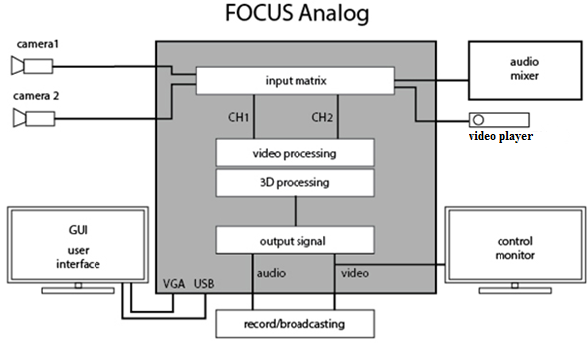
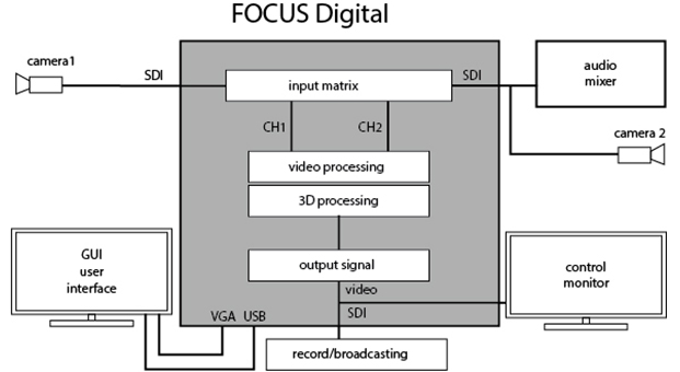
Initial setup of input-output equipment
In standard supply Focus Studios initial configuration of hardware is already done, but always possible situations requiring repeat or change some settings (for example, when upgrading or reinstalling). Usually, all the hardware has appropriate configuration software from the producer. Some boards have built-in protection against unauthorized use and require the installation of the corresponding keys (software or hardware), that allow or deny certain boards functionality (in particular, this applies to all cards series FD). Each producer shall submit own configuration utilities and documentation, and in this document will be considered only features concerning the use of different hardware in the virtual Focus Studio.
Before using the equipment properly in the software application Focus Studio usually it is required pre-configure - check or set the correct external commutation, types and signal formats, set the appropriate settings in the software interfaces, etc. Then you can start to the specific input-output settings in applications in a virtual Focus Studio (HotActions, HotActions Live, Presenter). This is, for example, internal commutation settings of sources, rear-projection, color correction, cropping, filtration and the like. These settings are rather universal and basically the same for all types of hardware input / output. Some exceptions are described in the relevant chapter devoted to the settings in the software environment of the studio.
Settings features of FDxxx boards for work in studio
(Here describes how to work with boards series FDExt (FD322/FD422/FD842). FD300 board dedicated a separate chapter).
Functionality of FD series boards that available to the user is determined by set registry keys (encrypted entries in the registry), corresponding to each specific card (all boards have an individual number). Availability of keys and other equipment are checked with the utility FDConfig2 (available after installing the drivers FDBoardsDrivers from the installation kit).
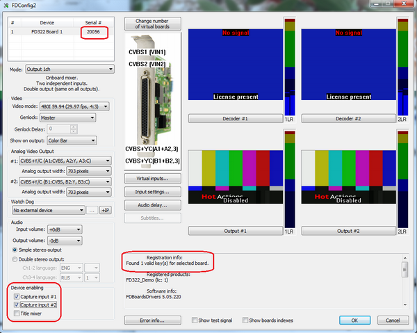
In the picture marked significant for the initial test fields - number of the board, the license presence and type, required for the correct operation settings (ASI disabling and mixer). For more information about boards and configuration utility you can read in the relevant technical documentation on the producer’s board.
In the studio Focus FD322 boards used for input / output analog signals with standard (SDTV) definition (two channels) and analog balanced / unbalanced audio. As this board has its own built-in input commutator, so it is required to make the correct choice of inputs related to a hardware connection. Another feature of these boards is the ability to adjust the model parameters on the input signal decoder.
FD422 boards are used for input / output digital signals SDI, as standard (2 channels) and high (1 channel) definition with embedded audio. Additional configuration signal setting isn’t provided, only the choice of the current format. The board can operate in a hybrid mode –to input as HD SDI (1 channel) and to output - SD SDI (1 channel).
FD842 boards are used for the multichannel input, up to 4 HD SDI channels at the same time, and for output - up to 2 channels of HD SDI (with embedded audio). Also it is possible to construct hybrid regimes (currently there are restrictions on the possible formats for use (only 50Hz, etc.)). Additional configuration of signals parameters also is not provided.
All these boards (unlike FD300) do not contain the integrated hardware audio mixer. Accordingly, the audio delay for synchronization with the video source control and final mix are produced by software tools of Focus Studio applications. Accordingly, work with sound is described in the relevant chapters of the documentation for applications of virtual Focus studio.
Input channels in the Focus studio are default plug DirectShow filters, which are created in the system when you install the driver boards. Working capacity of filters can be checked by standard system tools, even without launching applications studio Focus, if the need arises. Settings in the filters are minimal and are usually used by default.
Focus Studio output data stream is formed by software rendering module and sent in the board output or for further processing (e.g., coding for the transmission network). In the system can be installed at the same time a number of different input-output boards. Selecting an output device occurs in the Render Engine options dialogue.
Availability of different user input filters, formats and output devices is defined by registry keys of Focus studio software applications. All applications require the installation of hardware security USB-key (HASP) and the corresponding software license of registration keys. If the user does not see in the corresponding program selection dialogs installed boards, it may mean that there is no installed license (registration key) to use them, but not any malfunction.
Output modes setting in Focus studio on board FD842
For correct work of the studio in modes with HD inputs and HD outputs is necessary:
1. Launch the FDConfig2 utility
- a) enable the mode Single-SDI
- b) turn off the mixer on output.
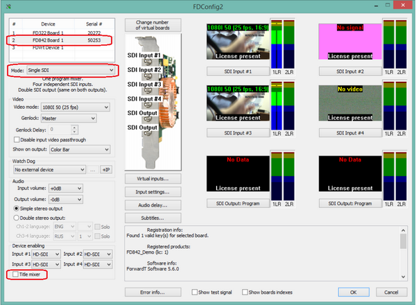
2. Run HotActions application
- a) In the dialogue «Render Options» Select the output device FD842 Board 1 Output 1
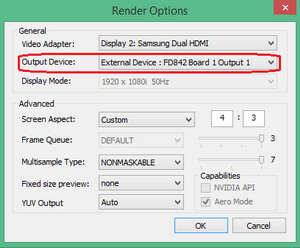
3. Video signal at the outputs must be №1 and №2
In this mode, the same output HD-SDI signal is served on the both output connectors. Similarly adjusted output for studio work with signals SD-SDI.
SD output setting of studio for FD842 board with HD inputs
1. Launch the utility FDConfig2
- a) Enable the mode HD-SDI + SD-SDI.
- b) Turn off the mixer on all outputs.
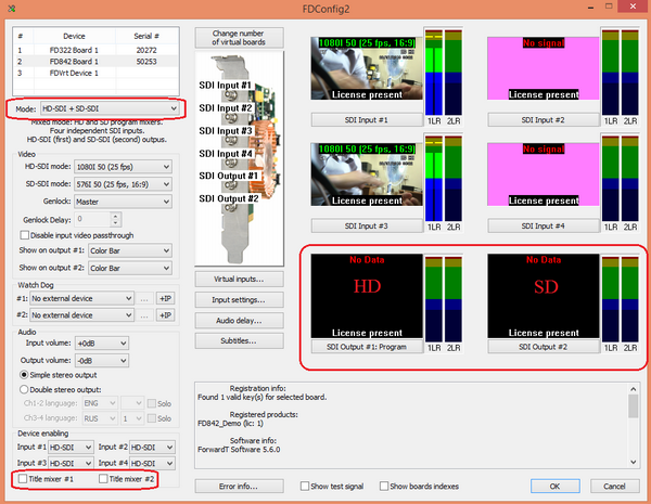
2. Run application HotActions.
- a) In dialogue «Render Options» select the output device FD842 Board 1 Output 2
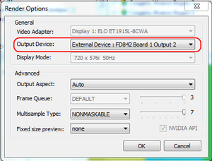
3. Output video signal should be №2.
In this mode, the output signal of the studio is served only to one output connector. Note: The word "Disabled" in the preview of FDConfig2 utility refers to the mixer appropriate output, which must be turned off to support the work with virtual studio.
The Black Magic boards setting for recording a signal from studio
1. At the control panel, you need to select the format of the input SDI signal
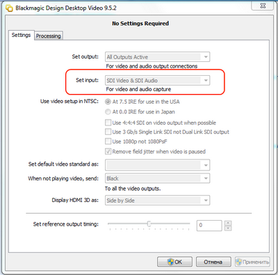
2. In an application that is used to input using the BM boards, check the coincidence of the resolution setting with the output of the studio.
Settings features of FD300 boards for studio
Before signal configuring in the application HotActions 3.0 it is recommended to configure the FD300 board in the application FD300 Configuration: specify the audio options on the audio device selected for this operating system (described in "Sound Settings" section 5.1 of this document). In case the transmission of video input signals and output the resulting video images in the studio provided through boards FD300 (SDI digital or analog signals), the program FD300 Configuration also is required to set their parameters: define the format, enable the option transmission through the filters Direct Show, specify the type of output and video synchronization mode.
Before working with video and audio signals in the virtual studio application HotActions 3.0, it is required to configure settings for work with these data on the FD300 boards in the application FD300 Configuration. Sound reproduction settings defined for output audio board ( "Sound Settings" section). Working with digital (SDI) and analog video signals is also required setting ( "Video Settings" section).
Sound Settings
Working with sound in a virtual studio, usually performed on the output board, i.e. the board with the highest logical number L in the list Boards'Indexes in the application FDConfig.
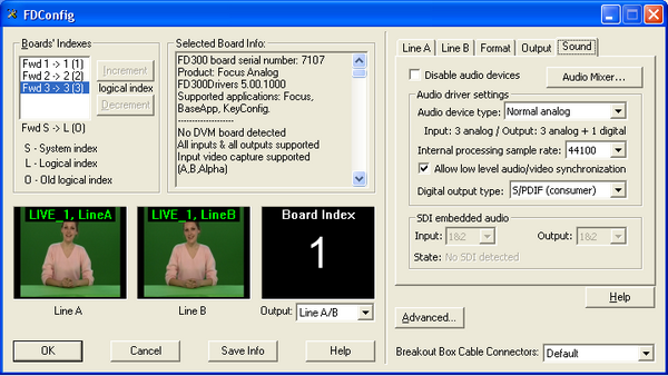
In the operating system one of the output devices of this board is selected as the default used for sound reproduction. To do this, from Start menu run Control Panel, from which opens an audio tuning dialog in System Sounds and Audio Devices. In the list of Default device of Play Sounds group in Audio tab of this dialogue should be chosen one of the sound output device of the output board. Usually selected first (FD300 Output 1 B3, for example).
In the Sound tab in the FDConfig window for output board have to be turned off the option Disable audio devices. In the same tab in the Audio device type list, select the number and type of input and output audio devices on the board. Parameter Internal processing sample rate determines the audio sample rate, the option Allow low level audio / video synchronization allows low-level audio and video synchronization. In the list of Digital output type selects audio signal transmitted by a digital output (if enabled).
After setting the parameters for working with audio signals connected to the board, further adjustment can be made by running the application FD300 Sound Control. In a virtual studio (application HotActions 3.0) Sound Mixer dialog invoked by clicking the button ![]() or menu command Tools. The detailed description of the dialogue can be found in "Sound Mixing through the expansion board FD300" chapter of this document or in the user guide for sound settings.
or menu command Tools. The detailed description of the dialogue can be found in "Sound Mixing through the expansion board FD300" chapter of this document or in the user guide for sound settings.
Video Settings
Setting of the input video signals
In work with video signals on the FD300 board for each of them, indicated in the Boards'Indexes by application FDConfig serial numbers Fwd1, Fwd2 and so on, in the list of TV Standard in the tab Format television signal format, transmitted to the board: PAL, NTSC or other, is assigned. In the list Image Size from the same tab, you can change the effective horizontal resolution - FullFull (720 pixels) or HalfFull (360 pixels).
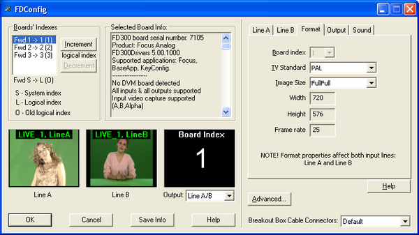
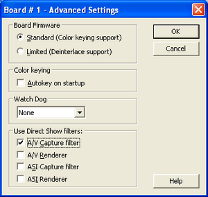
Working with video connections in a virtual studio (application HotActions 3.0) is carried out through the filter Direct Show. Therefore, for each board with the submitted work video signals in the application FDConfig must be enabled A / V Capture Filter in section Use Direct Show filters in dialogue Advanced Settings (Fig. 3), caused by pressing the button Advanced.
Setting of the video output signal mode
For outputting the result video in virtual studio board, that having the largest logical index L in the list Boards'Indexes in applications FDConfig, is used. Output video parameters defined for it in the tab Output.
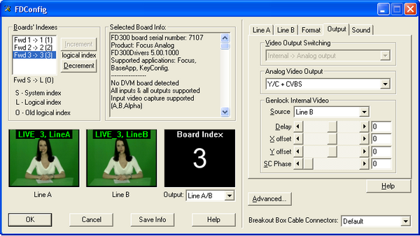
In the Video Output Switching specify the form in which the data will be supplied to the output encoder. These can be either internal video data from mixer Internal, or external digital data from Digital bus.
- Internal -> Analog output –the analog output mixer receives data; an external bus data is not used.
- Internal -> Analog output + Digital bus – the analogue output is receiving data from the mixer. These data are supplied to digital bus operating in the transmit mode, while the device connected to this bus must operate in receive mode. It can be used to organize the output in SDI format.
- Digital bus -> Analog output – the analogue output coming from an external digital bus; internal mixer data are not used.
In the list Analog Video Output select combination of analog video signals, which submitted to board output.
Connecting of video signals receivers made through the commutating device connected to the board. This could be a breakout cable or panel Breakout Box. For such connections on the device there is 4 connectors: CSYNC / CVBS, Y / GREEN / LUMA, U / BLUE / CVBS, V / RED / CHROMA. Below is a table describing the video signals from the list of Analog Video Output (Fig. 4) and matching these signals to connectors communicating device connected to the output board FD300. The following notation:
- CVBS - composite signal;
- Luma, Chroma – signal components Y/C (S-video);
- Y, U, V component signal components YUV;
- R, G, B – component signal components RGB;
- Sync – sync pulse signal;
- s – the presence of impurities in the sync pulse in the corresponding component
- ns – absence of sync pulse in the corresponding component.
| Video signal | Switching Device Connectors | |||
|---|---|---|---|---|
| RED
V/Chroma |
BLUE
U/CVBS |
GREEN
Y/Luma |
CVBS
CSYNC | |
| CVBS x 3
Three composite signal |
CVBS | CVBS | CVBS | |
| Y/C+CVBS
Signal Y/C (Luma/Chroma) and composite signal |
Chroma | Luma | CVBS | |
| 'YUV+CVBS
Component signal YUV and composite signal |
V | U | sY | CVBS |
| YUV+Sync
Component signal YUV with sync pulse on a single wire |
V | U | Y | Sync |
| nsRGB+Sync
Component signal RGB with sync pulse on a single wire |
R | B | G | Sync |
| YUV+sKey
Displayed fill and mask. Fill signal in the format of component signal YUV without synchronization in Y Mask signal in the format of a composite signal |
V
Fill |
U
Fill |
Y
Fill |
sKey
Key |
| ns(Key onY)UV+sY
Displayed fill and mask. Fill signal in the format of component signal YUV with sync Y Mask signal in the format of a composite signal without synchronization in Y |
V
Fill |
U
Fill |
Key
Key |
sY
Fill |
| nsRGB+Key
Fill signal in the format of component signal RGB without synchronization in G Mask signal in the format of a composite signal |
R
Fill |
B
Fill |
G
Fill |
sKey
Key |
| ColorBarY/C+CVBS
Displays a table of colored stripes. Signal Y / C (Luma / Chroma) and a composite signal |
Chroma | Luma | CVBS | |
| ColorBar YUV+CVBS
Displays a table of colored stripes. Component signal YUV and a composite signal |
V | U | sY | CVBS |
| ColorBar nsRGB+Sync
Displays a table of colored stripes. Component signal RGB with sync pulse on a separate line |
R | B | G | Sync |
| Double SDI
Used only for SDI-option when displaying fill and masks |
the analog output signal is incorrect | |||
Table 1 - Table of video outputs combinations
In the list of modes there are always all the possible combinations for a given studio configuration.
In the Source list in Genlock Internal Video section in Output tab in the application FDConfig (Fig. 4) for the video signal output board set timing mode to:
- Master – frequency of video output signal generated by the internal board generator doesn’t synchronized to any frequency of external video signal;
- Line A – frequency of video output signal synchronized to the frequency of video signal selected in the Input list in tab Line A;
- Line B - frequency of video output signal synchronized to the frequency of video signal selected in the Input list in tab Line B.
Delay regulator allows you to assign a value of video signal delay (in milliseconds) to compensate for the delay when it passes through the cable. The value set by default 0.
X offset and Y offset regulators define the horizontal and vertical displacement relative video to the sync signal, installed by default 0.
Sc Phase – color burst phase delay of sync signal defined by default 0. Used to synchronize the composite video signal.
Sound Mixing through the expansion board FD300
FD300 board has three stereo inputs and three stereo outputs (respectively 6 mono inputs and 6 outputs mono). On commutative cable or commutative panel connected to the board with a special cable there are special connectors for external audio sources and output signals from the board FD300.
In the studio, for configure modes of sound mixing of connected sources, designed Sound Configure dialog (Fig. 14), which appears by pressing a button ![]() on the toolbar of the main window or when you call it from the Tools menu. This dialogue provides audio mixing from any input to any output with varying volume and delays.
on the toolbar of the main window or when you call it from the Tools menu. This dialogue provides audio mixing from any input to any output with varying volume and delays.
Group of parametras in Options allows, using the drop-down list (Fig. 14, 1), choose the board to adjust. Number of values in this list is determined automatically depending on the number of boards FD300, installed in the system (Fig. 1).
Another drop down list of parameters group Options, (Fig. 14, 2), allows you to set the volume levels to minimum for all volume controls of dialogue (Fig. 14, 8, 9). Setting the option Show Meters (Fig. 14, 3) allows you to track the change in the signal in each of the inputs and outputs with help of the signal level.
Parameter Curr. Ratio: shows the current the audio sample frequency (in Hz). Sampling frequency of the input audio signal coincides with the output signals. You can change this setting by running the application FD300Configuration (HotActions 3.0 application before it is necessary to close) and selecting from the dropdown list Internal processing sample rate on the the Sound tab required sampling frequency ("Sound Settings" section, Fig. 1).
All mono-inputs of the board by default linked for stereo inputs (option Lock for each pair, for example, Fig. 14, 4). Input signal Level of stereo inputs may vary with any of the level regulators of its constituent mono inputs. Also for the second and the third stereo inputs switching on of options Mic. Boost (Fig. 14, 5) allows to switch on additional signal amplification.
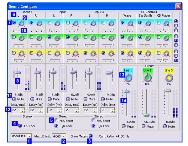
Each input of the board can be configured independently - with the help of the group, such as group Input1L (Fig. 14, 6) that is used to configure the first mono-board input (left channel first stereo input).
Options settings in this group includes audio mixing from this mono input to corresponding stereo output of board. For example, setting of the first switch in the group Input1L (Fig. 14, 7) comprises the mixing of mono input to the first stereo output. At the same time volume control (Fig. 14, 8) allows you to set the level of the signal sent to the corresponding stereo output. When you hover the cursor to the regulator (Fig. 14, 9) the help appears: on what output signal is served.
By default, all options in mono inputs groups settings are set so that the the mixing comes from a pair of inputs to their corresponding output. For example, the first and second mono inputs (i.e., the first stereo input) to the first stereo output Output1 and so on. It also emphasizes the fact that the inputs and outputs, corresponding to them by default, have the same color balance controls.
At default settings, the left channel of the first stereo input (Input1L) is completely served to the left channel stereo output, and the right channel of the first stereo input (Input1R) - completely to the right channel. This is ensured by the fact that the balance of the left channel of the stereo inputs (Fig. 14, 10) exhibited as possible to the left and right channel balance –as possible to the right. Regulators (for example, Fig. 14, 10) allow you to change the balance for each of the input channels.
Completely exclude separate entrance from the mixing of all output channels simultaneously is possible by setting an option Mute (Fig. 14, 11).
Also, for each mono-input in Delay field audio delay set between 1 frame to 1 second (in milliseconds) (Fig. 14, 12).
For each stereo output additionaly can be changed the balance (Fig. 14, 13), the volume level (Fig. 14, 14) or turned off output - option Mute.
Problems with the FD300 board
One or more boards are not detected in the system
If in the list of Board's Indexes settings applications of boards FD300 Configuration (Fig. 2) the number of records about FD300 boards does not match the number of cards installed in the system, you should check for the correct entries about boards in the dialogue Device Manager operating system.This dialog can be called sequential execution Start> Settings> Control Panel> System> Hardware> Device Manager.
If in section Sound, video and game controllers of this dialogue board can not be detected at all board, corresponding record SoftLab-NSK FD300C card is missing, then most likely, the board simply is not in contact with the slot physically. You must shut down the computer and check that all boards are seated tightly. It is also possible that the card is defective, in this case, contact the technical support department (see "Technical Support" section). If the board is found in the system, but is not identified as SoftLab-NSK FD300S Card, you need to take the following steps:
- Delete all incorrectly installed boards from the list of devices in the system. To do this, for each board you have to click on its icon by right-click and in the pop-up menu click Delete…
- Click on the name of a section by right-click and in the pop-up menu select Scan for hardware changes
- The system detects the new device and if the software has been installed correctly, install the appropriate drivers.
Technical Support
Comprehensive consultation on all matters relating to the Virtual Studio can be obtained by contacting our technical support department SoftLab-NSK company and Graphics at the following email address:
vrset@sl.iae.nsk.su или
vrset@softlab.tv
Tel: 7-383-332-5841
Skype: Focus_nsk
Novosibirsk